|
|


Amiga 1200 Modification Project
To use an Amiga 1200 or 500 there are some internal mods needed
Modifying an Amiga 1200 for laser show use
The laser scanner hardware needs a DC coupled audio signal to properly drive the scanner amps that make the galvo motors
point where they need to. This project details the modification of the Amiga 1200 audio output, which by design is an AC coupled
amp, to output DC audio signals. The internal mod to the Amiga is fairly simple, but the resulting DC output after modification
must also be DC shifted and converted to a bipolar signal. This is accomplished with another part of the project external to the
Amiga; the DC offset / bipolar amplifier. I used a schematic from the LaserFX website to build the circuit. That page (as well as
most of the site) is full of great info and is a must for some intense laser related website surfing. The article says this mod can only
be done on the Amiga 500 and several other models other than the 1200, but it actually does work perfectly with a properly
modified A1200. I have two A1200's that have done several hobby laser shows with this internal mod. If you happen to have an
Amiga 500 or one of the other models mentioned, try them out. I did originally modify a couple of A500's and used them for one
laser show, but I like the A1200's much better because they have hard drives, more memory, and they are faster (much faster if
they have accelerator cards installed). This page details the modification as well as the construction of the external offset/bipolar
amp. This is a project that requires a fair amount of electronics knowledge and experience to complete. It requires a soldering
iron with a micro tip as well as other tools that are usually owned by an electronics hobbyist. Good luck to you! Read on...
Let's get started - Open the 1200 and take a look inside
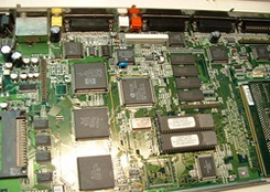
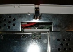
When the cover and the internal metal shield is removed, the Amiga 1200 main board is
revealed. The hard disk has also been removed prior to the photo being taken. There are
several screws that need to be removed to get the cover off, then the keyboard is unplugged
and removed. The white bar near the upper center of the picture is the keyboard connector.
The keyboard ribbon cable is removed by lifting at the edges of the connector until it clicks
up (just a little). The ribbon cable then comes out very easily. Behind this connector are the
audio connectors (red and white), and between those and the keyboard connector are the
coupling capacitors of interest to us. These must be bypassed to make a DC audio signal
available for our laser galvo amps.
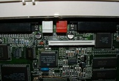
Here's a closer view of the capacitors, which are the round devices just to the lower left and
lower right of the two audio connectors. You can clearly see the keyboard connector there
too. Notice the very close proximity of the right side capacitor to the keyboard connector.
I chose to preserve the normal audio function of my Amigas, so I installed a separate connector for the DC outputs (two options are shown below). To accomplish this, wires or coaxial cables must be soldered to the surface mount pads on the positive side (closer to the keyboard connector) of each of the capacitors. Since the clearance of the capacitor to the right is so close to the keyboard connector, a micro tipped low wattage soldering iron must be used to avoid damaging it. This is close quarters work... be careful not to melt the keyboard connector.
I chose to preserve the normal audio function of my Amigas, so I installed a separate connector for the DC outputs (two options are shown below). To accomplish this, wires or coaxial cables must be soldered to the surface mount pads on the positive side (closer to the keyboard connector) of each of the capacitors. Since the clearance of the capacitor to the right is so close to the keyboard connector, a micro tipped low wattage soldering iron must be used to avoid damaging it. This is close quarters work... be careful not to melt the keyboard connector.
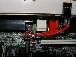
Here you see where the wires are soldered, as well as the option one connector. The
common (or ground) wire is soldered to the board's negative (ground) at the closest
available point, which was the mounting tang for the video connector. The wire is just a three
conductor ribbon cable, which kept the wires neat and out of the way. The other end is
soldered to a small three pin connector I had on hand. You can use practically any connector
you wish, as long as you have a mating connector for it, and it can fit somehow into the
Amiga housing. The wires are also insulated with heat shrink tubing. I have a few pictures
below of another connection method using a standard 1/8" stereo headphone jack.
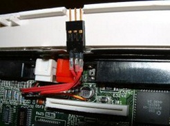
Here's another view showing the soldered connection between the right side capacitor and
the keyboard connector. Be extremely careful soldering here to avoid melting the connector.
The solder pads for the capacitors are easily visible, and can be soldered to if you have a
steady hand. If not, get an experienced steady handed friend to do it for you.
The connector is just super glued to the plastic of the lower case and a notch was filed (before attaching the connector) to allow insertion of the mating connector. The lower metal shield had to be trimmed down slightly to clear the connector also.
The connector is just super glued to the plastic of the lower case and a notch was filed (before attaching the connector) to allow insertion of the mating connector. The lower metal shield had to be trimmed down slightly to clear the connector also.
Here, the metal shield is being installed back into place. Notice the notched out section
directly behind the new connector. The metal shield is normally straight all the way across
the back, but I needed clearance for the connector, so I used a pair of tin snips to trim back
the metal to allow just enough clearance.
The metal shield is removed by bending all the metal tabs straight up (one shown to the left of the connector). This makes it easier to re-install the shield later. You can then bend them back over, or just leave them as they are. You might need to get in there again, you never know...
The metal shield is removed by bending all the metal tabs straight up (one shown to the left of the connector). This makes it easier to re-install the shield later. You can then bend them back over, or just leave them as they are. You might need to get in there again, you never know...
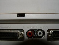
This rear view of the connector port shows how the notch looks. This was done using a small
pin file. The mating connector just fits into the rectangular opening so as not to allow it to be
plugged in wrong. There is no keying, so the connector can be plugged in either way. The
ground is on the center pin so the only thing that can happen is reversal of the X and Y axis
inputs to the galvo amp buffer. This may sometimes be desirable, so I didn't worry about it
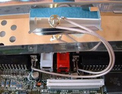
This is an alternative method (option 2) of wiring up the mod. I did this on a second Amiga
1200 I modified. This time I used some tiny coaxial cable I had on hand and made the other
end a standard mini stereo headset connector. It is mounted into a drilled 1/4" hole the back
of the Amiga, facing down. The center conductors are soldered to the capacitors and the
shields are soldered to the grounded rear connector tangs. Again, care must be taken not to
melt the keyboard connector while soldering to the capacitor. I didn't have to do any
trimming on the shield to mount this one. The coax cables are long enough to exit through
the keyboard cable opening.
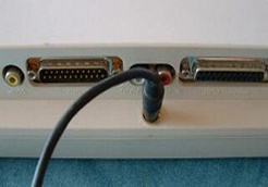
The Amiga is shown upside-down with the patch cable plugged in. I use a right angle
adapter now because the connector and cable extended to far down with the Amiga
right-side-up. The cable here goes to the DC offset amp shown below. Same goes with the
ribbon cable version.
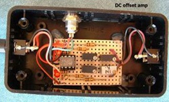
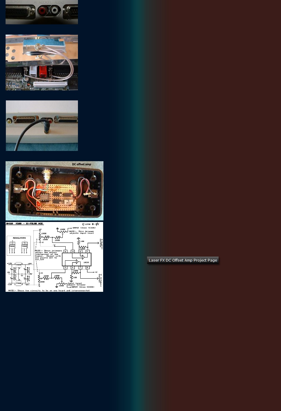
This is the DC bipolar amplifier / offset corrector as I built it. As mentioned at
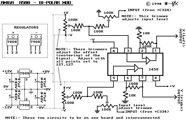
the top of this web page, The schematic can be found at the LaserFX website
along with detailed instructions. I used standard plain perf board to construct
the circuit on. The wiring on the underside is just point to point using wire-wrap
wire, and following the schematic.
The offset correction is necessary because the Amiga's modified output has a DC value when there is no signal. The galvo amps it will drive require zero volts when there is no signal. The connectors are for input from the Amiga, DC to power the circuit (middle), and output to the galvo amps.
As you can see, there is not much to this thing and it can be constructed in a very reasonable amount of time in any enclosure you so desire. If you prefer a PC board, there is a web site I have used a number of times, called Sunstone Circuits, that is great for do-it yourself PC board design. They used to have a simple pricing structure (I miss that) and lower prices, but their quality is still great. There are a number of other choices beside Sunstone, so shop around for the best value. As an alternative, you can do it yourself using materials available at various electronics supplies. I chose the simple method and stuck with point to point wiring (was anxious to get it working!).
DC Offset Amp Schematic from Laser FX article
Once you have completed this project, go download the Pangolin software
shown on the software page, install it on the Amiga 1200, connect your offset
amp between the 1200 and your laser scanner, and start experimenting.
Caution: you will loose sleep while playing with this once you have it 100%
functional! : )
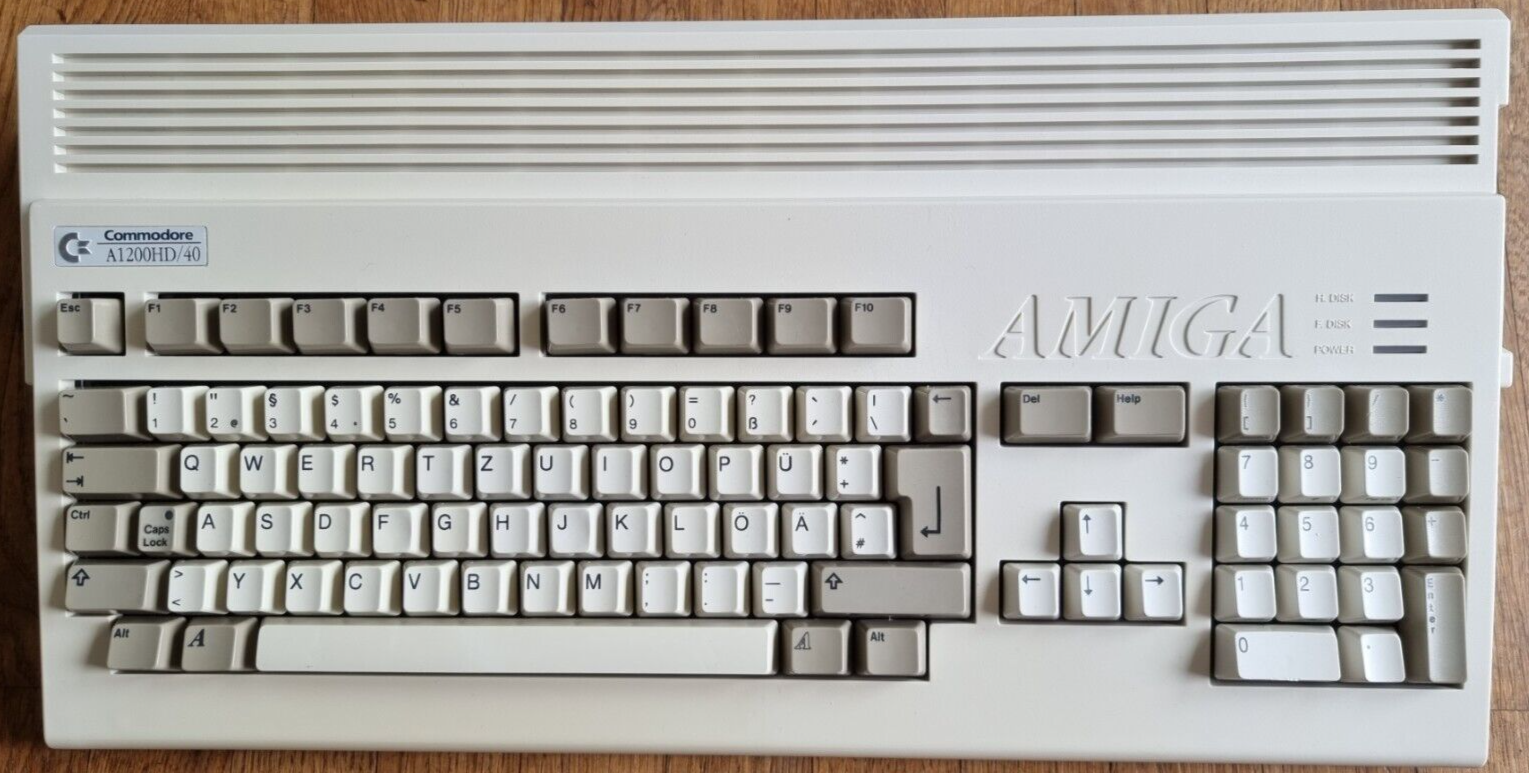
Pictured here is an Amiga 1200, the model that is modified
in this project. It is smaller (front to back and hight) than the
Amiga 500 but still has the 3.5" floppy drive on the right side
as well as a hard drive inside.


